

 Thanks: 0
 Likes: 0
 Needs Pictures: 0
 Picture(s) thanks: 0
Results 1 to 15 of 23
Thread: Weird Roof Plan
-
21st February 2007, 11:51 AM #1
 New Member


- Join Date
- Feb 2007
- Location
- Brisbane
- Posts
- 5
- Post Thanks / Like

 Weird Roof Plan
 Greetings All,
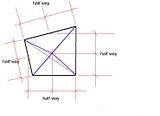
After building a deck around a tree my pole configuration (4 poles) for the roof is rombus shaped. I had originally planned to shade sail this area but want to build a gazebo style roof (4m X 3m) with shingles or slate. Will this present any unique challenges given that the poles are not square other than to have a weird shape ?
Cheers.Last edited by Spaski; 21st February 2007 at 03:01 PM. Reason: Picture
-
21st February 2007, 04:12 PM #2
GOLD MEMBER
- Join Date
- May 2003
- Location
- Kuranda, paradise, North Qld
- Age
- 63
- Posts
- 2,026
- Post Thanks / Like

Spaski
If the pokes form a true rhombus the the "top" two will be in a line parrallel with a line running through the "bottom" two. Thus if you run a beam on each pair and have the two beams the same length it will give you a rectangle to build on.
Mick"If you need a machine today and don't buy it,
tomorrow you will have paid for it and not have it."
- Henry Ford 1938
-
22nd February 2007, 12:31 AM #3
Sum ergo cogito (Cogito)
- Join Date
- Oct 2006
- Location
- Tallahassee FL USA
- Age
- 83
- Posts
- 0
- Post Thanks / Like
I don't see anything parallel to anything in the pic. I'd suggest placing the peak directly above the intersection of the quadrilateral's diagonals. This should give you a fighting chance of making the ridge members right. You should expect a lot of fiddling to get all the bevels fitted. This will be easier if you build the roof (framing at least) on the deck. Might have to loosen the corner fixings to lift it. If the poles aren't plumb, you should be able to make them plumb with a few hand winches (aka come-alongs).
For a true rectangular roof, use beams between two pairs of poles, and build a rectangluar frame (all four side) to span between those.
Good thing you didn't include the tree within the covered area!
JoeOf course truth is stranger than fiction.
Fiction has to make sense. - Mark Twain
-
22nd February 2007, 01:25 AM #4
GOLD MEMBER
- Join Date
- May 2003
- Location
- Kuranda, paradise, North Qld
- Age
- 63
- Posts
- 2,026
- Post Thanks / Like
I just had a look at the pic and it isn't a rhombus, so scrap my idea.

Mick"If you need a machine today and don't buy it,
tomorrow you will have paid for it and not have it."
- Henry Ford 1938
-
23rd February 2007, 07:45 AM #5
New Member
- Join Date
- Feb 2007
- Location
- Brisbane
- Posts
- 5
- Post Thanks / Like
Thanks Joe. Appreciate your ideas.
-
25th February 2007, 04:47 AM #6
SENIOR MEMBER
- Join Date
- Apr 2005
- Location
- Sydney
- Age
- 65
- Posts
- 882
- Post Thanks / Like
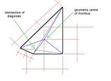
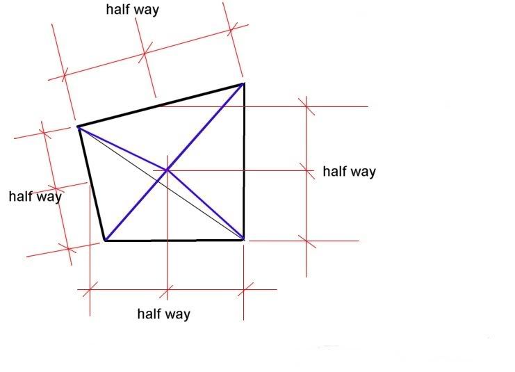
I would pitch it to a point at the geometric centre of the rhombus.
There is a difference between this point and the intersection of the diagonals as shown: -
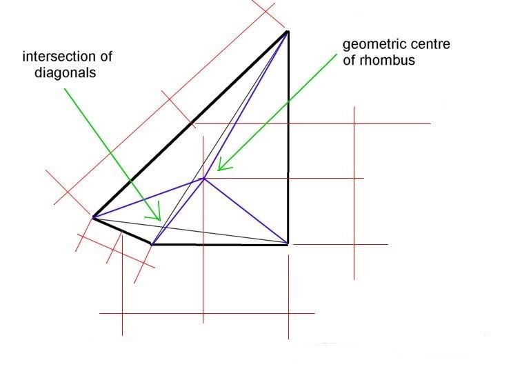
In a more exaggerated rhombus, the difference becomes more apparent : -
I can show you how to do the calculations for cutting the hips, or I can do them for you if you post your dimensions for the rhombus, the roof pitch, and at least one angle.
If that front corner is 90 degrees, then I don't need an angle.
And I'd build it in place. You could do it single handed.
-
25th February 2007, 11:26 AM #7
GOLD MEMBER
- Join Date
- May 2003
- Location
- Kuranda, paradise, North Qld
- Age
- 63
- Posts
- 2,026
- Post Thanks / Like
Rhombus
I thought a parallelogram was like a square that had been pushed in one corner to make it out of square, ie all sides equal lengths, oppposite sides parallel, but corners not 90 deg. Whereas a rhombus had four sides, two of which were parallel to each other. Of course it's been a few years since high school......

Mick"If you need a machine today and don't buy it,
tomorrow you will have paid for it and not have it."
- Henry Ford 1938
-
25th February 2007, 11:35 AM #8
SENIOR MEMBER
- Join Date
- Apr 2005
- Location
- Sydney
- Age
- 65
- Posts
- 882
- Post Thanks / Like
Yes, it's not a rhombus. I suppose you'd just call it an irregular polygon, and I'm not totally happy with my method of finding it's centre.
It gets you a lot closer than joining the diagonals, but it's not quite correct I've found.
I've posed the question on another forum that has a lot of geeks (no offense if you read this Assasinator_2. Thanks for the help ), but I suspect that the solution will be a quite complex method of averages, getting closer to the point, the more calculations that you do.
I'd imagine that it's something like halving all the angles. Drawing a polygon from their intersections, then halving the angles again, etc.
I should get a definitive answer soon.
-
25th February 2007, 11:41 AM #9
New Member
- Join Date
- Feb 2007
- Location
- Brisbane
- Posts
- 5
- Post Thanks / Like
Thanks John,
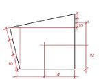
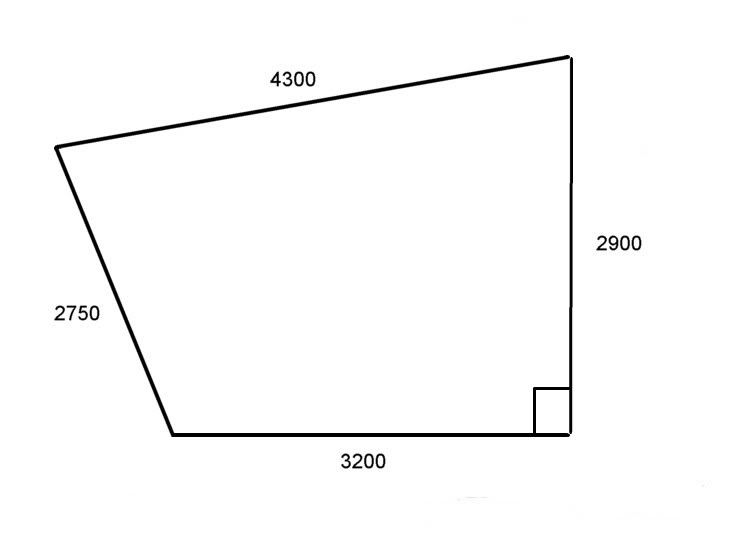
Outstanding. I will get back to you on the pitch and angle. Not yet decided. Dimensions are 2750 X 2900 X 4300 X 3200 with diagonals 4500 and 4850. It bares an uncanny resemblance to your diagram.
Cheers,
Brad
-
25th February 2007, 12:21 PM #10
SENIOR MEMBER
- Join Date
- Apr 2005
- Location
- Sydney
- Age
- 65
- Posts
- 882
- Post Thanks / Like
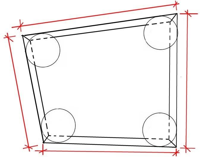
What you'll need are the dimensions to the outside corners of your beams. You can house the beams in flush, at the appropriate height by setting your power saw to the depth of the timber thickness. It looks like a 190X45 should do the trick at those spans. (Hmmm, perhaps a 240X45) scrub that. I've just noticed you've said that it's 4300mm. That would require some beam (if you want to stick to the code). Span table time.
Measure it at deck level using straightedges or stringlines as I've shown in this diagram : -
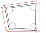
And check that the front corner is square using Pythagoras (3,4,5 or calculate a diagonal)
-
25th February 2007, 01:21 PM #11
SENIOR MEMBER
- Join Date
- Apr 2005
- Location
- Sydney
- Age
- 65
- Posts
- 882
- Post Thanks / Like
Well here it is, and as I suspected it's not all that simple. I think I could get my head around it with some concentration, but I think that my method would get you near enough.
Young Einstein, the physics guru has offered to crunch the numbers anyway, but I'm going to try to understand myself : - Originally Posted by Assasinator_2

-
25th February 2007, 05:04 PM #12
Novice
- Join Date
- Feb 2007
- Location
- Melbourne, Victoria
- Posts
- 21
- Post Thanks / Like
I know this isnt going to be the perfect solution, but there is another way to get the location of the centroid.
Make a scaled drawing of the shape of the roof (plan view) and cut the shape out of some even-density material, like cardboard. Put a pin through the cardboard somewhere near a corner (doesn't matter exactly where) and hang a plumb-line from this pin. Allow both to freely hang from the pin until they settle. Mark the line of the string on the cardboard.
Repeat this at another corner, and for a cross-check do it at a third location. The lines should all cross at the same point, and they will do so at the centroid of the object concerned.
For this kind of purpose the location found will be more than accurate enough. Measure it, scale it back up, and use trig from that point on.
That said, what you're really wanting to achieve is to spread the load evenly among the roof members. I assume you want to build this without 'ceiling' joists (ie, the bottom of your rafters aren't tied together) so the load coupling will be done by your fascias. You will have fascias in tension and with a bending load (good), and hip rafters in compression and with a bending load (potentially bad). The bending loads in the hip rafters are what you want to minimise and by shifting the centre of your roof you can vary those loads. As a punt, I'd have thought you could do this by minimsing the total length of all your hip rafters, but I'm not an engineer. Regardless, my question is whether the centroid gives you the minimum bending loads. I expect it DOES, but I couldn't say for sure. Pawnhead, any chance of taking that question back to your geeks?
Oh, and you'll want to tie your fascias and hip rafters together VERY well.
-
25th February 2007, 08:50 PM #13
SENIOR MEMBER
- Join Date
- Apr 2005
- Location
- Sydney
- Age
- 65
- Posts
- 882
- Post Thanks / Like
Your method looks alright (a bit 'howyagoin' though
) so long as it's a big enough piece of cardboard. it is the centre of gravity that we're looking for to give the wonky roof the most symetrical look possible.
The intersection of the diagonals would look quite wonky if the polygon was extremely irregular.
I think I've got my head around that formula, but I'll wait for confirmation of the dimensions and angles before I tackle it. I can post it in the other forums for Assasinator_2 to double check my calcs.If the perimeter beams are bolted off well to the posts, then it should be alright without a bottom chord (ceiling joist), but they will have a tendency to bow out as well as sagging. You'll need a pretty decent sized beam to span over four metres though. Originally Posted by ChipperChip
The thread I started, asking the question is here, but it's a private forum so you'd have to sign up (free).
It's a computer geeks forum, much larger than these forums (second largest in Australia behind Whirlpool forums), but I have no real interest in turbocharging my PC for gaming. I mainly go there for the heated debates about current events, the science forum, and the internet humour.
It's quite an interesting place if you can get over all the nerds and geeks (they're not everywhere there). There's a lot of very clever and successful people there.
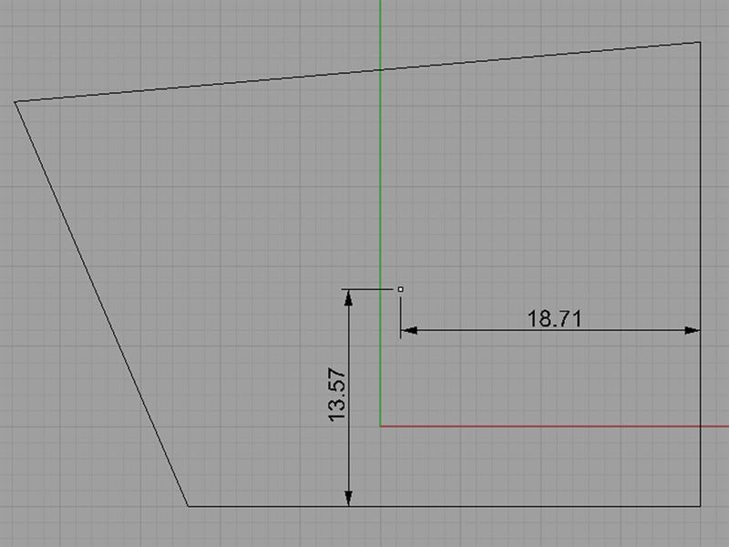
I posted this there going off the dimensions Spaski has already given: -And someone else plugged it into a program and came up with this : - Originally Posted by pawnhead
Originally Posted by TERRA Operative
Cheers
-
26th February 2007, 12:35 AM #14
Novice
- Join Date
- Feb 2007
- Location
- Melbourne, Victoria
- Posts
- 21
- Post Thanks / Like
Yeah, a bit howyagoin, but my Dad (an engineer) taught me that technique when I was about 8. It works every time, and as I said, for this application it's more than adequate. Bush engineering Originally Posted by pawnhead
I doubt there'd be much lateral deflection, actually - the hip rafters would have to buckle for that to happen. Your rafters should essentially just be transferring a dead load to your hip rafters and the perimeter beams. Lateral deflection would only happen if you had a ridge. Remember, hip ends are self-bracing, and this is like two back-to-back hip ends. Originally Posted by pawnhead
Where would you look it up? Isn't it structurally the same as a trimmer? I have a feeling that AS1684 only goes up to 3m spans for trimmers (going completely from memory) before calling for it to be 'designed according to engineering principles'. Originally Posted by pawnhead
Ah, I'd be at home there Originally Posted by pawnhead
I was a geek long before I became a carpenter. I googled the nickname as soon as I saw it and figured you must have been talking about the overclockers. Those blokes do some totally insane stuff. Years back I saw a double-barreled liquid nitrogen filled copper heat sink about a foot high to run a 1GHz cpu at 3.5GHz. It's like hot rods for geeks. I just used to build home-brew computers that had freaky CPUs and only ran home-cooked versions of Minix
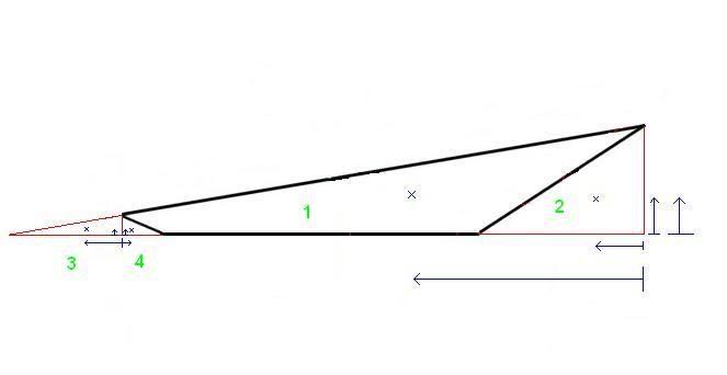
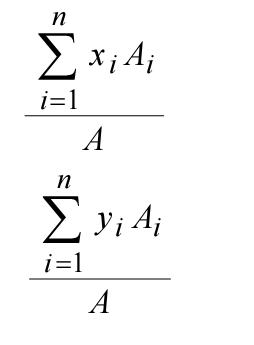
But back to the issue.. I'm still not completely convinced that the centroid will give you the best case for hip rafter compressive loads. It'd be dead easy to calculate the centroid for that roof though, if you do have one right angle. The shape is a rectangle with two right triangles attached. Use the right angle as your reference point (coordinates 0,0 ) and do the sums. Easy areas to calculate and easy 'sub-centroids' to plug in. What your geek described is just a weighted average.
Or you could get a piece of cardboard
-
26th February 2007, 01:09 AM #15
SENIOR MEMBER
- Join Date
- Apr 2005
- Location
- Sydney
- Age
- 65
- Posts
- 882
- Post Thanks / Like
Yeh, you're right there. Originally Posted by ChipperChip
Yeh they wouldn’t.Hyspan goes that far but you couldn’t use them outside. He could put in a cabletruss but it wouldn’t look all that crash hot. If it’s just a lightweight roof, then I’d just whack in a 300X50 chunk of HWD, and whack a cabletruss on it if it sags too much. Originally Posted by ChipperChip
There’s some mega geek building a rail gun there at the moment. Originally Posted by ChipperChip
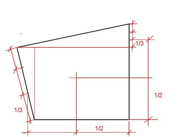
Probably something like this : - Originally Posted by ChipperChip
That's still not quite right though, because it doesn't take into account the overlapping of the triangles.
I do believe that the centre of gravity would be the best place for distributing hip loads evenly though.
edit : - No that's not right at all, the more that I think about it.
That formula above is the way to go I reckon. It makes sense when you think about it.


 Reply With Quote

Similar Threads
-
pergola roof over tile house roof
By Lbudgie in forum PERGOAS, GAZEBOS, STROMBELLAS & ROTUNDASReplies: 3Last Post: 24th March 2006, 05:58 PM -
Long span garage roof deck, more thoughts
By Wildman in forum DECKINGReplies: 4Last Post: 29th September 2004, 08:00 PM -
The Plan
By trevorZ in forum JOKESReplies: 1Last Post: 31st May 2003, 09:00 AM
Bookmarks